Rudi's Log Wagon
Some Interesting Facts
Did you know that 1 cord of mixed hardwood weighs 6500 pounds? Yep, 3.25 tons!
Did you know that 1 cord of mixed softwood weighs 2500 pounds?
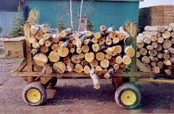
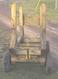
In the picture above the wagon is carrying an almost full load which would be
6 foot x 3 foot high x 4 foot wide of mixed hardwood. (green) This would equate
to about 72 cubic feet which is in between 3/5ths and 2/3rds of a cord.
That would mean the wagon is carrying in the vicinity of 3000 pounds with existing
load and up to 4000 pounds of wood if it was a full load! Not too shabby I guess.
Project History
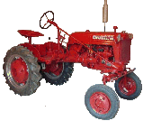
One of the reasons that I really wanted a Cub was to be able to complete basic chores
around my property that are repetitious year after year. This includes cutting and
hauling my winter firewood. In years past, I have had to depend upon my Father-in-law which
made for great times together, but I always had to plan around his schedule and not around mine
which has serious health issues that have to be factored in. So I decided when I finally got Ellie-Mae
that I would try to either purchase or fabricate the implements/accessories/tools that I needed
to complete whatever chore needed to be done. Hence the creation of my Logging Wagon.
Keep in mind that what follows is a wagon designed to haul 4 foot firewood on a reasonably smooth
logging road. It is not designed to go cross country. For that kind of application a steel frame is
essential. This observation being based on 20 years of experience hauling firewood with my Father-in-law and his
Massey.
I needed something that would be light enough so that it could be used by both
Ellie-Mae or my Craftsman Ride-on, yet strong enough to actually be usefull and carry at least 1/2 cord
of wood. Anything less would be just a toy and not be economical to use. Another consideration when
planning this project was my lack of welding capabilities - in other words - I cannot weld yet! Cost also
played a part in the design of this wagon. So, this necessitated utilizing fabrication principles that I was familiar with. Being a cabinetmaker
obviously dictated that I should construct my wagon out of wood, just as they did in the old days, yet incorporate
some new design principles. I have over the course of the last few years, been priviledged to see some really nice
wagons built by my Father-in-Law, professionals and some chums of mine, which played a large part in the design. I really have
them to thank for some of the ideas.
What follows is my feeble attempt at creating a sturdy yet light and dependable wagon for under $100.00 Cdn. Most of the
material I used was left over from my deck project, the wheels were scavenged off of scrapped snowblowers which I got
for about $5.00 Cdn each, the hitch was made by a friend of mine from scrap steel, although I did buy the square tube
for the hitch. The most expensive parts were the flange bearings which came complete with grease nipples (zerk's) and were about
$9.00 Cdn each. A detailed bill of materials will follow at the end of the document. All errors and ommissions are my fault entirely, and should you find any, please let me know so that
I may correct them. The scale of the drawings are indicated on each detail or page and vary from full size to
1/4"=4". I also hope that this will be of some use to my fellow Cubbers.
Oh, just as an aside, it took much longer to do the working drawings than it took to build the wagon!
One thing that has always been difficult is to build something from drawings when the principles are not always familiar. So, I have included the narrative as well to possibly help those who like me, sometimes are specific skill challenged for lack of a better term.

The Project
The primary material for constructing the Logging Wagon is #1/Select or Better, Pressure Treated 4" x 4" nominal lumber with a few 2" x 4" pieces scabbed in to increase either thickness of a member or to provide clearance. The actual dimensions for nominal 4" x 4" stock is 3-5/8"x3-5/8". Please confirm that the lumber available in your local area is this size. If it differs then some modification of the dimensions will be required.
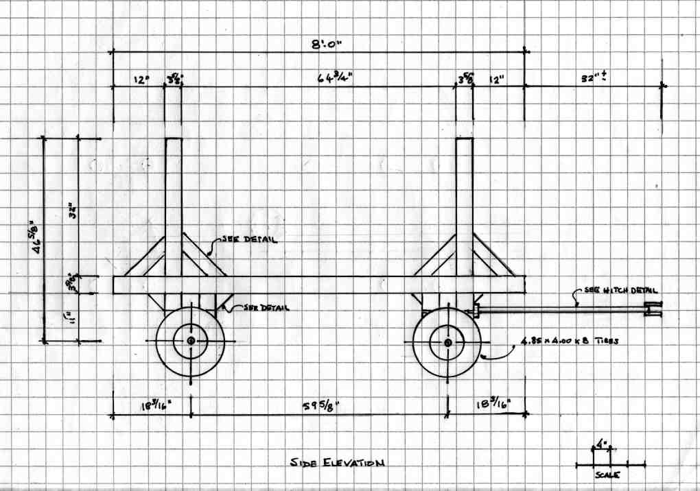
The side elevation is kind of self explanitory, nothing terribly complicated - yet!
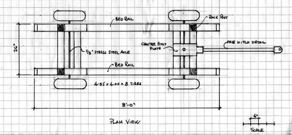
One of the first decisions I had to make was in regards to the axles. What size? Which material? At first I thought just ordinary cold roll steel rod say 3/4" or so would suffice. Oooops, I don't think so. After discussing it with a local steel supplier, they advised me to consider something called Stress Steel. It was only a few pennies more per pound but would provide much more strength especially in deflection which would be the primary force on the axle and not be too brittle. Sooo, Stress Steel it is. Then what type of bearing? Would a pillow block work? Would a 2 piece Pressed Steel Flange type bearing suffice, or should I elect to use the much sturdier Flange Mount Bearings and what size? I figured for the load, a 7/8" Stress Steel axle would be more than enough, so that is what I purchased. Another plus for this particular style bearing is that they come equipped with a grease nipple or for our friends south of the boarder a zerk fitting. Unfortunately, choosing this size necessitated changing my original design somewhat to accomodate the increased dimensions of the 7/8" Flange Bearing over the 3/4" Bearing I had originally envisioned.
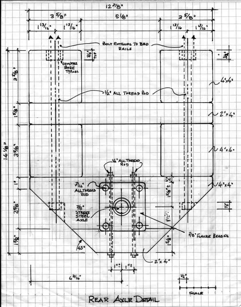
As you can see the Axle details depict the modification that I used to
accomodate the larger size of the 7/8" Flange Bearing. Normally,
scabbing would not be ideal, however, in this case it was the only
solution. Using a 6" x 6" would just make the axle assembly way too
heavy and cumbersome, as well as increase the price by a factor of 2
or more.
To add the 2" x 4" member after cutting to size I used a good waterproof
exterior grade glue, clamped and let sit for 24 hours to obtain maximum
strength. To aid in the layup I also used my 2" air nailer to position
the pieces prior to clamping. An air nailer will prove mighty usefull in
this project.
The next step is to lay out the location of the Flange bearing, mark
and drill all holes including the hole for the axle itself. I would
suggest making this hole slightly larger than 5/8", say 21/32" or
11/16" which would allow for expansion and negate the binding on the
axle that the expansion will cause. Mount the Flange Bearing with
7/16" all thread rod cut at 4-1/2" approximately taking into consideration
extra length to account for washers, lock washers and nuts. Ensure to use
lock washers and if desired lock nuts. Once the flange bearing is mounted, the next step is to locate and drill the holes for the
1/4" all thread rod. Install the rods making sure that lock washers
are used on both ends to ensure a very tight fit. Again and if desired lock nuts may be used.
Note: Although the front and rear axles do differ, the stock is
basically identical for both and I would suggest cutting all these
pieces at the same time. Also, do the glue up simultaneously as well.
One note of caution - pre-drill the 1/2" holes prior to cutting the mitres, this
will greatly simply the job later. Also, lay out and pre-drill all the
other 1/2" holes at this time as well. Saves on setup time. Preferrably
this would be done on a Drill Press which makes it much easier, but if you
do not have a Drill Press or access to one, a portable 1/2" drill can be used.
If you do use the portable drill, take your time, go slow. The bits used
are large (ships auger, forstner style, do not use a spade bit!) and can
wander quite easily not to mention break your wrist if the bit grabs a
hidden knot. Where indicated in the drawings, please drill the counterbored holes
prior to the 1/2" holes. A 7/8" or 1" speed bit or forstner should be used
for this operation. Now cut the 45 degree mitres where indicated.
Remember, although it is not shown in great detail in the preceding and following
details, the 1/2" all thread rod must be carried through the bed rails. Where
the rod exits the bed rail, the hole must be counterbored to ensure that the washers, lock washers
and nuts do not protrude past the surface of the rail. The posts sit on top of one
set of nuts and the braces sit atop the other set. If the rod protrudes past
the top of the bed rail, grind the rod until flush. Again, and if desired lock nuts may be used.
You will notice that there is a 1/2" difference in the height of the front axle
compared to the rear axle. This is to accomodate the centre pivot plate and also
negated having to run the 2" x 4" through the planer. In practise, it makes no
difference at all to the performance of the wagon.
Pay particular attention to the fact that the 1/2" all thread rod does not
extend thru to the bed rail in one piece, but is actually two separate items.
Also, this will necessitate extra counterbored holes to accomodate the extra
washers, lock washers and nuts.
As well, please note that all of the 2" x 4" stock is mitred on both ends. You may
eliminate the mitered edges on the filler stock under the centre pivot, but
the mitres on the ends of the axle ensure proper clearance when turning whilst
traversing bumps.
At this point, mount the bed rail assembly to the rear axle assembly and to the
top section of the front axle assembly. This is achieved easily if the bed rail
section is inverted and resting on a pair of benches or saw horses. The bottom
section of the front axle assembly will be mounted after the center
pivot plate is constructed. Pay close attention to ensuring that the axle's
are centered on the bed rail assembly, or there may be difficulties encountered
when the front axle is turned.
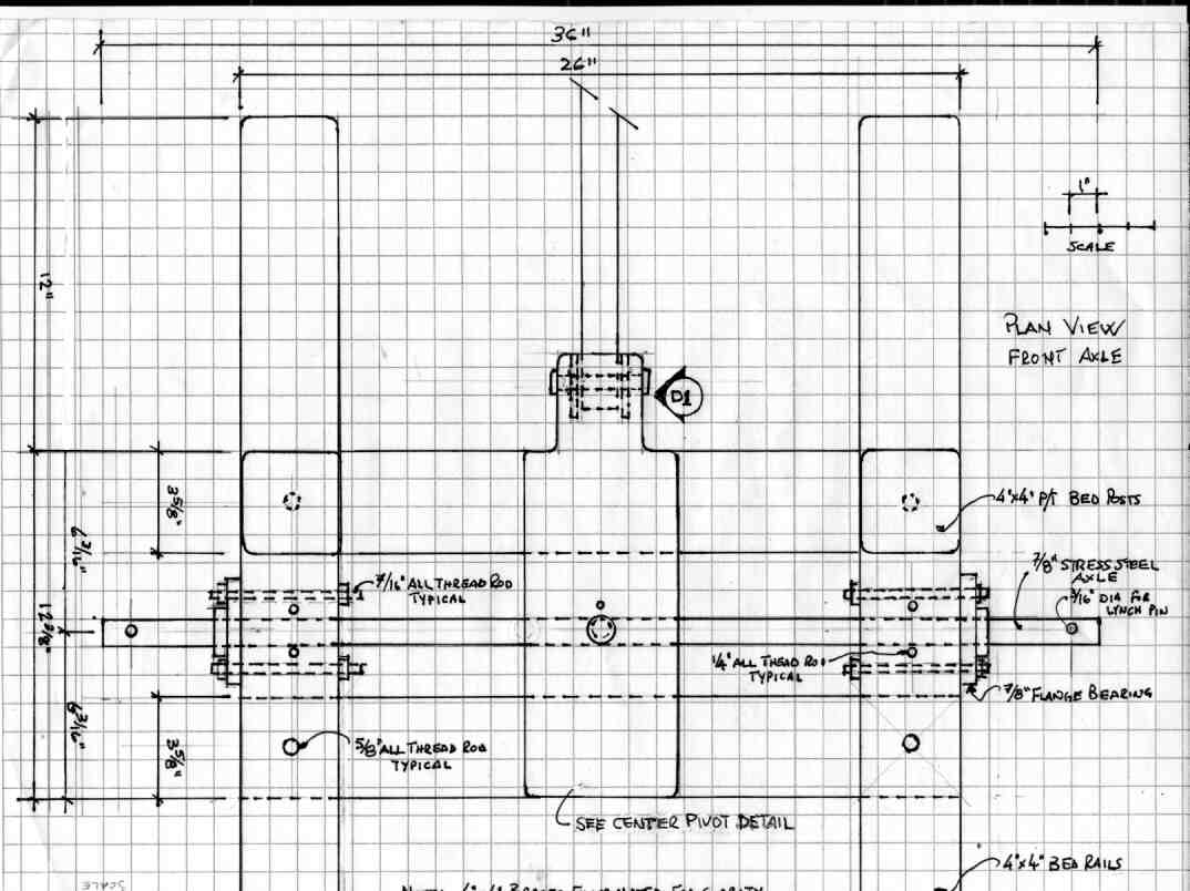
Just a couple of notes here. The axle length may vary depending on the type of wheels you intend to use. The position where the hole for the lynch pin will also vary, as will the diameter.

Cut the braces as shown. Refer to the Side Elevation and the picture of the wagon as to the placement of the braces. The braces are secured by #8 x 3-1/2" Deck Screws and are also glued with a good exterior waterproof glue. Tack in place with your air nailer if one is available. Be sure to drill pilot holes for the screws so that the braces do not split.
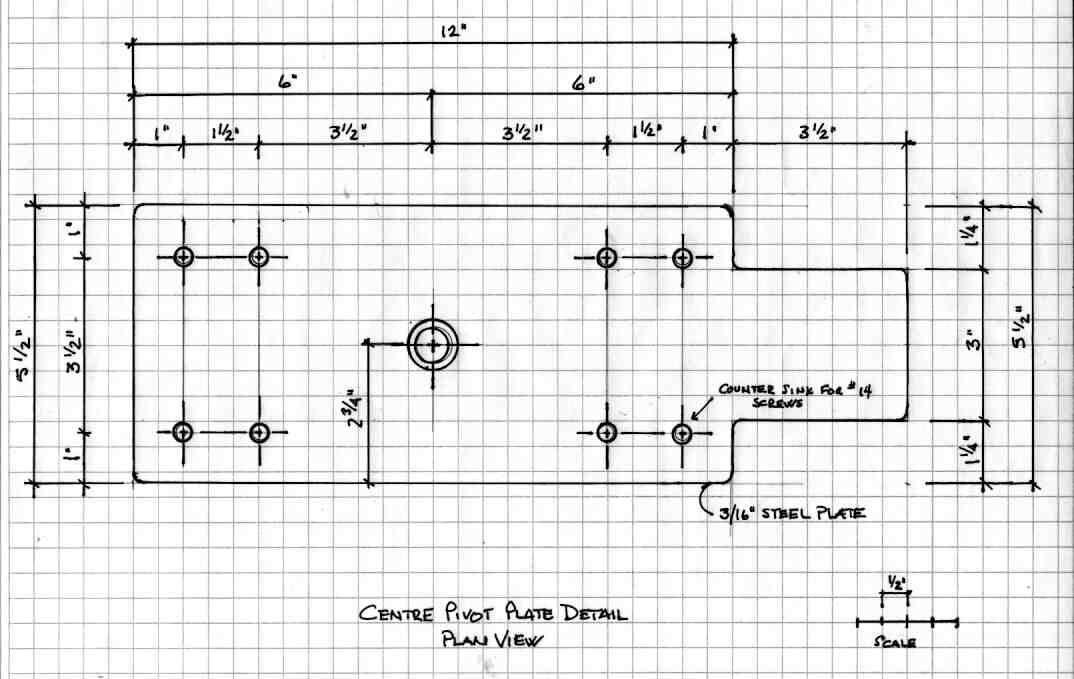
The centre pivot plates (2 required) are constructed from 3/16" plate
steel. The top plate may be made from one single piece of plate steel
or may be made by welding the tongue section, (shown below) to the pivot
plate itself. The bottom plate is a mirror image the top plate minus
the tongue.
The pivot pin is constructed thusly - a 5/8" bolt is cut to length (shaft
should be 5/8" long to account for the washer) and spot welded in 3 places
to the bottom plate. The bottom plate does not incorporate the tongue.
Ensure that a washer is placed on the bolt next to the head, then the top
section of plate which incorporates the tongue, followed by the bottom plate.
The washer is then spot welded to the head of the bolt. This allows the top
plate to turn freely over the bottom plate. Insert the grease nipple into
a properly sized pre-drilled hole. This only needs to be a pressed in fitting.
The resulting 1/8" gap allows for grease to lubricate the two mating surfaces.
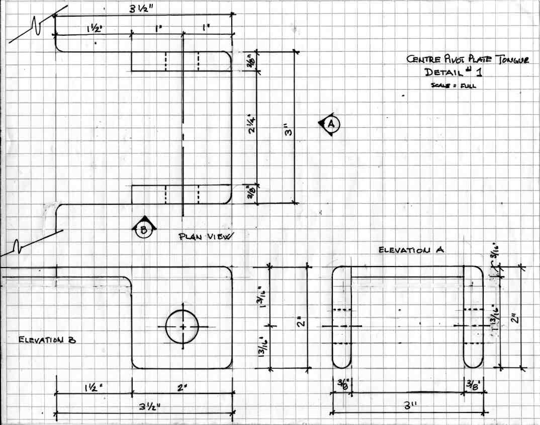
The tongue is comprised of three pieces whether or not it is integral with the pivot plate or will be welded to the pivot plate after. As shown the vertical surfaces which are drilled to accept a 5/8" bolt/pin (as shown above) are let into the plate. The vertical pieces are made from 3/8" stock as compared to 3/16" for the plate. Lay out and pre-drill pilot holes in the inside corners,to allow for easier cutting with a cut-off wheel. With the cut-off wheel, remove the excess stock. Weld the side pieces to the plate.
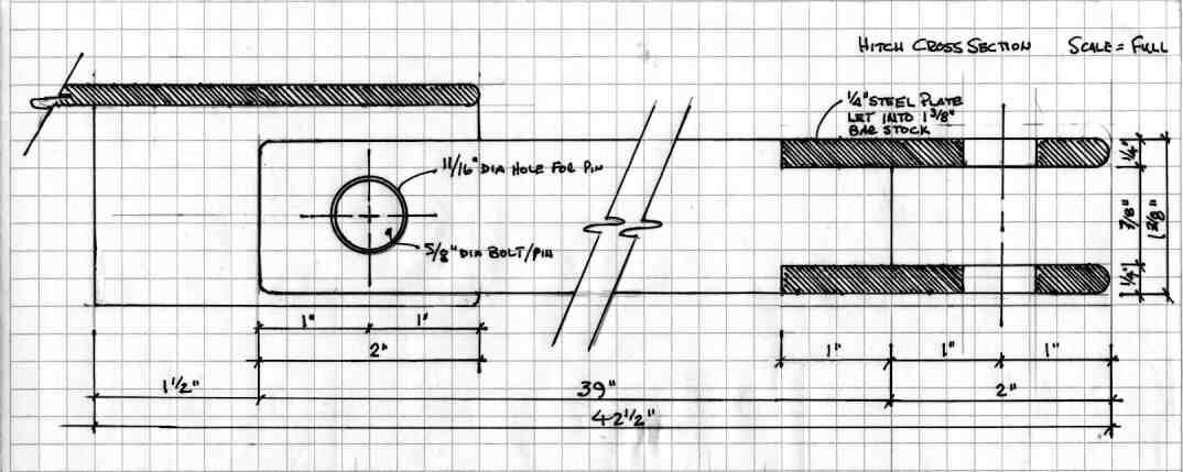
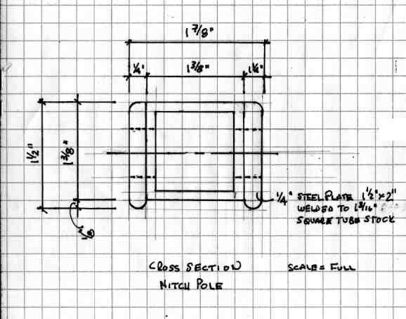
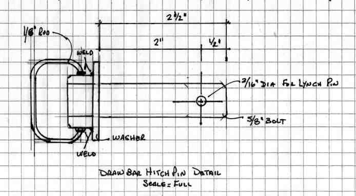
The hitch pole is relatively simple and is comprised of 5 separate pieces.
As shown below, a 2" x 1-1/2" x 1/4" plate is welded to both sides of the
1-3/8" square tube stock at the end where it will be mated with the pivot
plate tongue. An 11/16" hole is drilled thru to accept the hitch pin, as
described above and the plan shown below. Round off all sharp edges to
prevent binding.
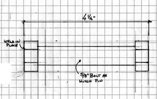
At the furthest end of the pole, 2 pieces of 3" x 2" x 1/4" is let into
tube stock and welded in place. Prior to welding, an 11/16" hole is drilled
1" from the end to accept a standard 5/8" diameter hitch pin to connect to the drawbar.
Also, these two pieces are rounded to remove sharp corners. The exact profile
is left up to you.
As shown above, construct a pin to connect the hitch pole to the hitch tongue.
Weld only after the two pieces have been connected.
The center pivot plate assembly can now be mounted to the front axle assembly
with the #14 1-1/2 Robertson screws. Ensure that the heads are perfectly
flush. If the heads are not perfectly flush, a little judicious use of a
grinding wheel will be called for. Nice thing about the Robertsons, you
can grind off a bit and still not lose the integrety of the screw or diminish
your ability to remove the screw if required. A little care is all that is
needed.
To finish the wagon, I applied 2 liberal coats of 10W30 motor oil.
Which brand and whether regular or synthetic is entirely up to you. I have found
that treated or untreated wood, if oiled, can be left outside for years
without serious deterioration provided every couple of years you re-coat with
oil.
I have not included a drawing of the tool box as it will vary from person to
person depending on their requirements. My tool box primarily was built to
hold a 1 gallon gas can, 1 gallon jug of chain oil, chain saw, pulp hook,
files, wrenches and a few other items, including a 2 litre bottle of water or
two. The dimensions are 12" x 12" x 36" and the box is constructed from
1/2" preassure treated exterior grade plywood and finished with 10W30 oil.
As you can see in the picture, I have also drilled a 3/8" hole in the side
of the box to accomodate the fiberglass extension that is used to guage
4 foot logs.

List of Materials
List of Materials
The following is a complete list of all the materials used aside from normal shop supplies such as nails, glue, sandpaper etc. For our US friends, the term Robertson indicates a specialized screw which we have been using for about 80 years in Canada. Over the last 20 years or so, McFeeley's Square Drive has been gaining in popularity in the US. In my opinion based on almost 40 years in the trades, Robertson or Square Drive are the only screw to use as they resist stripping unlike standard or phillips head screws.
| Framing | 4" x 4" x 8'-0" | Pressure Treated #1 or Better | 8 | $3.25 | $26.00 |
| Framing | 2" x 4" x 8"-0" | Pressure Treated #1 or Better | 1 | $2.05 | $2.05 |
| Rod | 1/4" x 4'-0" | All-Thread | 1 | $0.25 | $1.00 |
| Rod | 7/16" x 8'-0" | All-Thread | 1 | $0.30 | $2.40 |
| Rod | 1/2" x 10'-0" | All-Thread | 1 | $0.35 | $3.50 |
| Bolt | 5/8" x 4" | Standard | 3 | $0.30 | $0.90 |
| Nut | 5/8" | Standard | 3 | $0.03 | $0.09 |
| Flat Washer | 5/8" | Standard | 3 | $0.03 | $0.09 |
| Nut | 1/2" | Standard | 32 | $0.05 | $1.60 |
| Flat Washer | 1/2" | Standard | 32 | $0.02 | $0.64 |
| Lock Washer | 1/2" | Standard | 32 | $0.02 | $0.64 |
| Nut | 7/16" | Standard | 32 | $0.04 | $1.28 |
| Flat Washer | 7/16" | Standard | 64 | $0.02 | $1.28 |
| Lock Washer | 7/16" | Standard | 64 | $0.02 | $1.28 |
| Nut | 1/4" | Standard | 16 | $0.03 | $0.48 |
| Flat Washer | 1/4" | Standard | 16 | $0.02 | $0.32 |
| Lock Washer | 1/4" | Standard | 16 | $0.02 | $0.32 |
| Screws | #8 x 3-1/2" | Robertson Deck - Dipped | Box of 100 | $5.00 | $5.00 |
| Screws | #14 x 1-1/2" | Robertson | 16 | $0.625 | $1.00 |
| Steel Plate | 3/8" x 2" x 6" | Standard | 1 | $0.50 | $0.50 |
| Steel Plate | 1/4" x 2" x 6" | Standard | 1 | $0.50 | $0.50 |
| Steel Plate | 3/16" x 5-1/2" x 26" | Standard | 1 | $1.50 | $1.50 |
| Steel Tubing | 1-3/8" x 1-3/8" x 39" | Standard Square | 1 | $2.50 | $2.50 |
| Fitting | your preference | Grease Nipple or Zerk | 1 | $0.05 | $0.05 |
| Flange Bearing | 7/8" | Princess Auto #3870041 | 3 | $8.99 | $35.96 |
| Pin | 1/4" | Lynch | 4 | $0.4475 | $1.79 |
| Tires and Rims | 4.85 x 4.00 x 8 | Carlisle | 3 | $5.00 | $20.00 |
